Showing posts with label Fluid flow operation. Show all posts

Wednesday, 28 November 2018

CONTINUITY EQUATION

Continuity equation
  • The continuity equation is a mathematical expression for the law of conservation of mass.
  • The equation of continuity is useful for calculating the velocity of a fluid flowing through pipes of different diameters.
It states that for a steady flow system, the rate of mass entering the flow system is equal to that leaving as accumulation is either constant or nil in the flow system under steady conditions

  • Rate of mass entering the flow system = ρ1 u1 A1
  • Rate of mass entering the flow system = ρ2 u2 A2
  • According to the law of conservation of mass

Mass entering the tube = Mass leaving the tube
per unit time       per unit time


  • This is the equation of continuity.
  • It is applicable to compressible as well as incompressible fluids.
  • when ρ1 = ρ2

where
Continuity equation

Wednesday, 23 November 2016

AFFINITY LAWS OF PUMP

The Affinity Laws of pump
  • The Affinity Laws of centrifugal pumps or fans indicates the influence on volume capacity, head (pressure) and/or power consumption of a pump or fan due to
  1. change in speed of wheel - revolutions per minute (rpm)
  2. geometrically similarity - change in impeller diameter
  • Hence, the Affinity Laws are mathematical expressions that define changes in pump capacity,head, and BHP when a change is made to pump speed, impeller diameter, or both.
  • Affinity laws are useful when an existing pump must be modified ti give a higher or lower head or different capacity
  • The Affinity Laws are valid only under conditions of constant efficiency.
According to Affinity Laws:Capacity, Q: changes in direct proportion to impeller diameter D ratio, or to speed N ratio:


Head, H: changes in direct proportion to the square of impeller diameter D ratio, or the square of speed N ratio:
BHP: changes in direct proportion to the cube of impeller diameter ratio, or the cube of speed ratio:
  • Where the subscript: 1 refers to initial condition, 2 refer to new condition
  • If changes are made to both impeller diameter and pump speed the equations can be combined to:

Thursday, 13 October 2016

POWER AND EFFICIENCY OF CENTRIFUGAL PUMP

Power and efficiency of centrifugal pump
Brake Horse Power (BHP) and Water horsepower (WHP)

  • The work performed by a pump is a function of the total head and the weight of the liquid pumped in a given time period.
Pump input or brake horsepower (BHP) is the actual horsepower delivered to the pump shaft.
Pump output or hydraulic or water horsepower (WHP) is the liquid horsepower delivered by the pump.
  • These two terms are defined by the following formulas.

where
  • Q = Capacity in gallons per minute (GPM)
  • HT = Total differential head, ft
  • Specific gravity= Specific gravity of liquid
  • Efficiency = Pump efficiency, %

  • The constant 3960 is obtained by dividing the number or foot-pounds for one horsepower(33,000) by the weight of one gallon of water (8.33 pounds). 

The brake horsepower or input to a pump is greater than the hydraulic horsepower or output due to the mechanical and hydraulic losses incurred in the pump.

  • Therefore the pump efficiency is the ratio of these two values.
Best Efficiency Point (BEP)
  • The Head, NPSHr, efficiency, and BHP all vary with flow rate, Q.

Best Efficiency Point (BEP) is the capacity at maximum impeller diameter at which the efficiency is highest.

Significance of BEP

  • BEP as a measure of optimum energy conversion
  • When sizing and selecting centrifugal pumps for a given application the pump efficiency at design should be taken into consideration.
  • The efficiency of centrifugal pumps is stated as a percentage and represents a unit of measure describing the change of centrifugal force (expressed as the velocity of the fluid) into pressure energy.
  • The B.E.P.(best efficiency point) is the area on the curve where the change of velocity energy into pressure energy at a given gallon per minute is optimum; in essence, the point where the pump is most efficient.
  • The operation of a centrifugal pump should not be outside the furthest left or right efficiency curves published by the manufacturer.
  • Performance in these areas induces premature bearing and mechanical seal failures due to shaft deflection, and an increase in temperature of the process fluid in the pump casing causing seizure of close tolerance parts and cavitation.
  • BEP is an important parameter in that many parametric calculations such as specific speed, suction specific speed, hydrodynamic size, viscosity correction, head rise to shut-off, etc. are based on capacity at BEP.
  • Many users prefer that pumps operate within 80%to 110% of BEP for optimum performance.
Specific Speed
Specific speed as a measure of the geometric similarity of pumps

  • Specific speed (Ns) is a non-dimensional design index that identifies the geometric similarity of pumps.
  • It is used to classify pump impellers as to their type and proportions.
  • Pumps of the same Ns but of different size are considered to be geometrically similar,one pump being a size- factor of the other.

Specific speed Calculation

  • The following formula is used to determine specific speed:
where
  • Q = Capacity at best efficiency point(BEP) at maximum impeller diameter, GPM(gallons per meter)
  • H = Head per stage at BEP at maximum impeller diameter, ft
  • N = pump speed, RPM
  • As per the above formula, it is defined as the speed in revolutions per minute at which a geometrically similar impeller would operate if it were of such a size as to deliver one gallon per minute flow against one-foot head.
  • Specific speed should be thought of only as an index used to predict certain pump characteristics.
  • The specific speed determines the general shape or class of the impellers.

Wednesday, 5 October 2016

NET POSITIVE SUCTION HEAD

Net Positive Suction Head (NPSH)
  • Power supplied to the pump depend on the difference in the pressure between discharge and suction and is independent of the pressure level.
  • There is no effect on pump when suction pressure is below atmospheric pressure or well above it, as long as the fluid remains liquid.
  • But if suction pressure is only slightly greater than the vapor pressure, some liquid may flash to vapor inside to pump, a process called cavitation, which greatly reduces the pump capacity.
  • If the suction pressure is actually less than the vapor pressure, there will be vaporization in the suction line, and no liquid can be drawn into the pump.
  • To avoid cavitation, the pressure at the pump inlet must exceed the vapor pressure by certain value called net positive suction head (NPSH)
Hence, Net Positive Suction Head or NPSH for pumps can be defined as the difference between liquid pressure at pump suction and liquid vapor pressure, expressed in terms of height of liquid column.
  • Net positive suction head (NPSH) may refer to one of two quantities in the analysis of cavitation.
    1. The Available NPSH (NPSHA): A measure of how close the fluid at a given point is to flashing, and so to cavitation.
    2. The Required NPSH (NPSHR): The head value at a specific point (e.g. the inlet of a pump) required to keep the fluid from cavitating.
Net Positive Suction Head Required, NPSHr

  • Pumps can pump only liquids, not vapors
  • The satisfactory operation of a pump requires that vaporization of the liquid being pumped does not occur at any condition of operation.
  • This is so desired because when a liquid vaporizes its volume increases very much.
  • For example, 1 ft3 of water at room temperature becomes 1700 ft3 of vapor at the same temperature.
  • This makes it clear that if we are to pump a fluid effectively, it must be kept always in the liquid form.
  • Rise in temperature and fall in pressure induces vaporization
  • The vaporization begins when the vapor pressure of the liquid at the operating temperature equals the external system pressure, which, in an open system is always equal to atmospheric pressure.
  • Any decrease in external pressure or rise in operating temperature can induce vaporization and the pump stops pumping.
  • Thus, the pump always needs to have a sufficient amount of suction head present to prevent this vaporization at the lowest pressure point in the pump.
  • NPSH as a measure to prevent liquid vaporization
  • NPSH required is a function of the pump design and is determined based on actual pump test by the vendor.
  • NPSHr increases as capacity increases
  • The NPSH required varies with speed and capacity within any particular pump.
  • The NPSH required increase as the capacity is increasing because the velocity of the liquid is increasing, and as anytime the velocity of a liquid goes up, the pressure or head comes down.
  • The NPSH is independent of the fluid density as are all head terms.
Net Positive Suction Head available, NPSHa
  • Net Positive Suction Head Available is a function of the system in which the pump operates.
  • It is the excess pressure of the liquid in feet absolute over its vapor pressure as it arrives at the pump suction, to be sure that the pump selected does not cavitate.
  • It is calculated based on system or process conditions.
  • The formula for calculating the NPSHa is as below

where

hps= pressure head i. e. absolute pressure at surface of reservoir converted into head
hs= static suction head
hvps= vapor pressure head
hfs= friction head 

Significance of NPSHr and NPSHa
  • The NPSH available must always be greater than the NPSH required for the pump to operate properly.

PERFORMANCE PARAMETER OF CENTRIFUGAL PUMP

Performance parameter of centrifugal pump
The key performance parameters of centrifugal pumps are 
  1. Capacity
  2. Head
  3. BHP(Brake horse power)
  4. BEP (Best efficiency point)
  5. Specific speed

Capacity
Capacity means the flow rate with which liquid is moved or pushed by the pump to the desired point in the process. 
  • It is commonly measured in either gallons per minute(gpm) or cubic meters per hour (m3 /hr). 
  • The capacity usually changes with the changes in operation of the process. 
  • The capacity depends on a number of factors like: 
  1. Process liquid characteristics i.e. density, viscosity 
  2. Size of the pump and its inlet and outlet sections 
  3. Impeller size 
  4. Impeller rotational speed RPM 
  5. Size and shape of cavities between the vanes 
  6. Pump suction and discharge temperature and pressure conditions
  • The effect on the flow through a pump by changing the outlet pressures is graphed on a pump curve.
  • As liquids are essentially incompressible, the capacity is directly related with the velocity of flow in the suction pipe. 
  • This relationship is as follows:
where
  • Q= capacity
  • V = velocity of flow
  • A = area of pipe
Head
The pressure at any point in a vertical column of the liquid can be caused due to its weight. The height of this column is called the static head and is expressed in terms of feet of liquid. 
  • The same head term is used to measure the kinetic energy created by the pump.
In other words, head is a measurement of the height of a liquid column that the pump could create from the kinetic energy imparted to the liquid. 
  • The head is not equivalent to pressure. 
  • Head is a term that has units of a length or feet and pressure has units of force per unit area or pound per square inch. 
  • The main reason for using head instead of pressure to measure a centrifugal pumps energy is that the pressure from a pump will change if the specific gravity (weight) of the liquid changes, but the head will not change. 
  • Since any given centrifugal pump can move a lot of different fluids, with different specific gravities, it is simpler to discuss the pumps head and forget about the pressure.
  • A given pump with a given impeller diameter and speed will raise a liquid to a certain height regardless weight of the liquid. 
Pressure to Head Conversion formula 
  • The static head corresponding to any specific pressure is dependent upon the weight of the liquid according to the following formula
There are different type of head, which are as follows


1. Static Suction Head (hS ) :
Head resulting from elevation of the liquid relative to the pump centerline is called static suction head. 

  • If the liquid level is above pump centerline, hS is positive. 
  • If the liquid level is below pump centerline, hS is negative. 
  • Negative hS condition is commonly denoted as a “suction lift” condition 

2. Static Discharge Head (hd):
It is the vertical distance in feet between the pump centerline and the point of free discharge or the surface of the liquid in the discharge tank.
3. Friction Head (hf):
This head required to overcome the resistance to flow in the pipe and fittings. 
  • It is dependent upon the size, condition and type of pipe, number and type of pipe fittings, flow rate, and nature of the liquid.
3. Vapor Pressure Head (hvp):
  • Vapor pressure is the pressure at which a liquid and its vapor co-exist in equilibrium at a given temperature. 
When the vapor pressure is converted to head, it is referred to as vapor pressure head, hvp
  • The value of hvp of a liquid increases with the rising temperature and in effect, opposes the pressure on the liquid surface, the positive force that tends to cause liquid flow into the pump suction i.e. it reduces the suction pressure head.
4. Pressure Head (hp):
Pressure Head must be considered when a pumping system either begins or terminates in a tank which is under some pressure other than atmospheric. 
  • The pressure in such a tank must first be converted to feet of liquid. 
  • Denoted as hp, pressure head refers to absolute pressure on the surface of the liquid reservoir supplying the pump suction, converted to feet of head. 
  • If the system is open, hp equals atmospheric pressure head.
5. Velocity Head (hv):
Velocity head refers to the energy of a liquid as a result of its motion at some velocity ‘v’. 
  • It is the equivalent head in feet through which the water would have to fall to acquire the same velocity, or in other words, the head necessary to accelerate the water. 
  • The velocity head is usually insignificant and can be ignored in most high head systems.
  • However, it can be a large factor and must be considered in low head systems.
6. Total Suction Head (HS ):
  • The suction reservoir pressure head (hpS ) plus the static suction head (hS ) plus the velocity head at the pump suction flange (hVS) minus the friction head in the suction line (hfS ). 
HS = hpS + hS + hvS – hfS 

The total suction head is the reading of the gauge on the suction flange, converted to feet of liquid.
7. Total Discharge Head (Hd):
  • The discharge reservoir pressure head (hpd ) plus static discharge head (hd) plus the velocity head at the pump discharge flange (hvd ) plus the total friction head in the discharge line (hfd). 


Hd = hpd + hd + hvd + hfd 

The total discharge head is the reading of a gauge at the discharge flange, converted to feet of liquid. 
8. Total Differential Head (HT):
It is the total discharge head minus the total suction head  


HT = Hd + HS (with a suction lift) 
HT = Hd - HS (with a suction head)

Thursday, 29 September 2016

CENTRIFUGAL PUMP

Centrifugal pump
  • A centrifugal pump is one of the simplest pieces of equipment in any process plant.
  • Centrifugal pumps are the most common type of dynamic pump or kinetic pump and are used most often in applications with the moderate-to-high flow and low head.
  • These pumps all rely on the centrifugal force as the fundamental principle by which they operate.
Centrifugal pump increase the mechanical energy of the liquid by centrifugal action
Its purpose is to convert the energy of a prime mover (an electric motor or turbine) first into velocity or kinetic energy and then into pressure energy of a fluid that is being pumped. 
 
The energy changes occur by virtue of two main parts of the pump, the impeller, and the volute or diffuser. 
  • The impeller is the rotating part that converts driver energy into the kinetic energy.
  • The volute or diffuser is the stationary part that converts the kinetic energy into pressure energy.
Working of centrifugal pump
The process liquid enters the suction nozzle and then into the eye (center) of a revolving device known as an impeller. 
  • When the impeller rotates, it spins the liquid sitting in the cavities between the vanes outward and provides centrifugal acceleration.
  • As liquid leaves, the eye of the impeller a low-pressure area is created causing more liquid to flow toward the inlet. 
  • Because the impeller blades are curved, the fluid is pushed in a tangential and radial direction by the centrifugal force. 
  • The faster the impeller revolves or the bigger the impeller is, then the higher will be the velocity of the liquid at the vane tip and the greater the energy imparted to the liquid.
Components of Centrifugal Pumps
  • A centrifugal pump has two main components: 
A rotating component comprised of an impeller and a shaft.
A stationary component comprised of a casing, casing cover, and bearings. 


    Stationary Components 
    1. Casing
    • Casings are generally of two types: volute and circular. 
    • The impellers are fitted inside the casings. 
    • Volute casings build a higher head.
    • Circular casings are used for low head and high capacity. 
    • A volute is a curved funnel increasing in area to the discharge port. As the area of the cross-section increases, the volute reduces the speed of the liquid and increases the pressure of the liquid. 
    • One of the main purposes of a volute casing is to help balance the hydraulic pressure on the shaft of the pump. However, this occurs best at the manufacturers recommended capacity. 
    • The circular casing has stationary diffusion vanes surrounding the impeller periphery that converts velocity energy to pressure energy. 
    • Conventionally, the diffusers are applied to multi-stage pumps.
    • The casings can be designed either as solid casings or split casings. 
    • Solid casing implies a design in which the entire casing including the discharge nozzle is all contained in one casting or fabricated piece. 
    • A split casing implies two or more parts are fastened together. 
    • When the casing parts are divided by horizontal plane, the casing is described as horizontally split or axially split casing. When the split is in a vertical plane perpendicular to the rotation axis, the casing is described as vertically split or radially split casing. Casing Wear rings act as the seal between the casing and the impeller.
    2. Suction and Discharge Nozzle
    • The suction and discharge nozzles are part of the casings itself. 
    3. Seal Chamber and Stuffing Box
    • Seal chamber and Stuffing box both refer to a chamber, either integral with or separate from the pump case housing that forms the region between the shaft and casing where sealing media are installed. 
    • When the sealing is achieved by means of a mechanical seal, the chamber is commonly referred to as a Seal Chamber. 
    • When the sealing is achieved by means of packing, the chamber is referred to as a Stuffing Box. 
    • Both the seal chamber and the stuffing box have the primary function of protecting the pump against leakage at the point where the shaft passes out through the pump pressure casing. 
    • When the pressure at the bottom of the chamber is below atmospheric, it prevents air leakage into the pump. 
    • When the pressure is above atmospheric, the chambers prevent liquid leakage out of the pump. 
    • The seal chambers and stuffing boxes are also provided with cooling or heating arrangement for proper temperature control. 
    3. Bearing housing
    • The bearing housing encloses the bearings mounted on the shaft. 
    • The bearings keep the shaft or rotor in correct alignment with the stationary parts under the action of radial and transverse loads. 
    • The bearing house also includes an oil reservoir for lubrication, constant level oiler, jacket for cooling by circulating cooling water.
    Rotating Components
    1. Impeller
    The impeller is the main rotating part that provides the centrifugal acceleration to the fluid. 
    • The number of impellers determines the number of stages of the pump. 
    • A single-stage pump has one impeller only and is best for low head service. 
    • A two-stage pump has two impellers in series for medium head service. 
    • A multi-stage pump has three or more impellers in series for high head service. 

    2. Shaft
    • The basic purpose of a centrifugal pump shaft is to transmit the torques encountered when starting and during operation while supporting the impeller and other rotating parts. 
    • It must do this job with a deflection less than the minimum clearance between the rotating and stationary parts.

    Wednesday, 10 August 2016

    TYPES OF PUMP

    Pump
    • A pump is a device that moves fluids (liquids or gases), or sometimes slurries, by mechanical action.
    • The basic purpose of pump is to transfer fluid or liquid or gases or slurries from a lower level to higher level.
    • The pumps increase the mechanical energy of the liquid, increasing its velocity, pressure or elevation or all three
    • Pump are widely used in variety of application
    • Pump exist in a variety of shapes and sizes, depending on their intended function.
    • When the flowing fluid is a gas, the pump is typically referred to as a compressor.
    • There are two major classes of pump
    1. Positive displacement pump
    2. Centrifugal pump
    Positive displacement pump
    • It is the first major class of pump. 
    • In this pump, a definite volume of liquid is trapped in chamber, which is alternately filled from the inlet and emptied at a higher pressure through the discharge.
    • Positive displacement units apply pressure difference directly to the liquid by a reciprocating piston, or by rotating members which form chambers alternately filled by and emptied of the liquid. 
    • Positive displacement pumps are a category of pumps designed to move fluid at a steady rate through a system. 
    • These pumps are able to handle viscous fluids, which flow at lower speeds and create more resistance, more efficiently than kinetic (dynamic) pumps. 
    • There are two sub classes of positive displacement pumps.
    1. Reciprocating pumps
    2. Rotary pumps
    Reciprocating pumps
    • In reciprocating pumps, the chamber is a stationary cylinder that contain a piston or plunger or diaphragm.
    • They utilize a piston, plunger or diaphragm which draws fluid in (upstroke) and pushes it out (downstroke), using check valves to regulate and direct flow through the system.
    • In a reciprocating pump, a volume of liquid is drawn into the cylinder through the suction valve on the intake stroke and is discharged under positive pressure through the outlet valves on the discharge stroke. 
    • The discharge from a reciprocating pump is pulsating and changes only when the speed of the pump is changed. This is because the intake is always a constant volume. 
    • Often an air chamber is connected on the discharge side of the pump to provide a more even flow by evening out the pressure surges. 
    • Reciprocating pumps are often used for sludge and slurry.
    • There are three example of reciprocating pumps
    1. Piston pumps
    2. Plunger pumps
    3. Diaphragm pumps
    Piston pumps


    • In piston pump, liquid is drawn through an inlet check valve into the cylinder by the withdrawal of a piston and then is forced out through a discharge check valve on return stroke.
    • Most piston pumps are double acting with liquid admitted alternately on each side of the piston so that one part of the cylinder is being filled while the other is being emptied.
    • The piston may be motor driven through reducing gears , or a steam cylinder may be used to drive the piston rod directly
    • The maximum discharge pressure for commercial piston pumps is about 50 atm. 
    Plunger pumps
    • For high pressure plunger pumps are used 
    • A heavy walled cylinder of small diameter contains a close fitting reciprocating plunger, which is merely an extension of the piston rod
    • At the time of stroke plunger fills nearly all space in the cylinder.
    • Plunger pumps are single acting and usually are motor driven
    • They can discharge against a pressure of 1500 atm or more.
    Diagram pumps
    • In a diagram pump, the reciprocating member is a flexible diaphragm of metal, plastic or rubber
    • This eliminates need for packing or seals exposed to the liquid being pumped, a great advantage when handling toxic or corrosive liquid
    • Diagram pumps handle small to moderate amount amounts of liquid, up to 100gal/min, and can develop pressure in excess of 100 atm 
    Rotary pumps
    • A wide variety of rotary positive displacement pumps are available.
    • They bear such names as gear pumps, lobe pumps, screw pumps, cam pumps, and vane pumps.
    • Rotary pumps do  not contain check valve.
    • Rotary pumps operated best on clean, moderately viscous fluid, such as light lubricating oil.
    • In rotary pumps discharge pressures up to 200 atm or more can be attained.


    Monday, 21 September 2015

    CLASSIFICATION OF FLUID

    Classification of fluid

    Ideal fluid
    Ideal fluid is incompressible and possesses no viscosity.
    • Such a fluid is only an imaginary fluid.
    • All existing fluids have some velocity.
    Real fluid : -
    A fluid that possesses viscosity is known as a real fluid.

    • In actual practice, all fluids are real fluids
    Newtonian fluid
    A real fluid in which the shear stress is directly proportional to the rate of shear strain (or velocity gradient) is called Newtonian fluid.
    Non – Newtonian fluids
    A real fluid in which the shear stress is not proportional to the rate of shear strain (or velocity gradient) is called Non -Newtonian fluid.
    Ideal plastic fluid
    A fluid in which the shear stress is more than the yield value and the shear stress is proportional to the rate of shear strain (or velocity gradient) is called ideal plastic fluid.

    Monday, 14 September 2015

    VISCOSITY / DYNAMIC VISCOCITY

    Viscosity/Dynamics viscosity
    It is defined as the property of fluid which offers resistance to the movement of one layer of fluid over another adjacent layer of the fluid.

    • Two liquid layers at distance y and (y+dy) from the surface have velocity values u and (u+du) 
    • The top layer causes a shear stress on the adjacent lower layer while the lower layer causes a shear stress on the adjacent top layer.
    • The shear stress is proportional to the rate of change of velocity with respect to y.
    • Mathematically

    Or

    Where,

      = is constant for proportionality and is known as the coefficient of dynamic viscosity
     = is called velocity gradient

    • M. K. S. unit : kgf-sec/m3
    • C. G. S. unit : dyne-sec/m2 , 1 dyne-sec/m2 is called one poise
    • S. I. unit : newton-sec/m2 = Ns/m2

    KINEMATIC VISCOSITY

    Kinematic viscosity
    Kinematic viscosity is the ratio of the two physical properties of the fluid.
    It is also defined as the ratio between the dynamic viscosity and density of a fluid.
    Mathematically


    • M. K. S. and S. I. unit: - m2/s
    • G. S. unit: - cm2/s
    • One cm2/s is known as one stroke
    • one stroke = One cm2/s = (1/100)2/s= 10-4  m2/s
    • The practical unit of kinematic viscosity is centistoke
    • 1 centistoke = (1/100) stoke

    Wednesday, 9 September 2015

    SPECIFIC GRAVITY

    Specific gravity

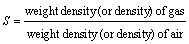
    It is defined as the ratio of weight density of a fluid to the weight of density(or density) of a standard fluid.
    • The standard liquid is water and the standard gas is air. It is a dimensionless quantity.
    • Mathematically
    • For liquids


    • For gases

    SPECIFIC WEIGHT AND SPECIFIC VOLUME

    Specific weight and specific volume

    Specific weight
    • It is weight of fluid per unit volume.
    • M. K. S. unit: kg/m3
    • S. I. units: N/ m3
    • To convert in SI units multiply (MKS) by 9.81. the specific weight of water is 9810 N/ m3
    • Specific weight of a fluid varies due to
    1. Change of gravity 
    2. Effect of pressure and temperature 
    Specific volume
    • It is defined as volume per unit mass
    • M. K. S. unit: m3/ slug
    • S. I. units: m3/ kg